Electronics DC Circuit Analysis App, Electronics AC DC Circuit Analysis App

Description

This document explains the workings of 2 Android Apps, Electronics DC Circuit Analysis App and the Electronics AC DC Circuit Analysis App. The Apps allows you to draw a circuit on a grid, to solve the circuit and display the voltages, and currents. The DC version Electronics DC Circuit Analysis App allows this for DC Circuits, Electronics AC DC Circuit Analysis App (coming soon) allows for solution of both type of circuits DC or AC, and will also contains some additional special features. The branches entered may be voltage sources, current sources, resistors, or 1 of 4 types of controlled sources. The AC version will allow for inductors, capacitors, impedance and admittance branches. The Apps have 4 main modes; [Nodes] [Branches] for entering data, [Solve] for computing the solution to the circuit, and [Display] for displaying the data.

Getting Started


Fig. 1

The screen will come up blank (Fig. 1) The Mode button will be blue, and it will say DC Circuit on the black bar above that button.
Note: If the Mode button does not say [Node], you should press that button, and on the screen that pops up press [Node]
Note If the screen is not clear, then you can clear it by pressing the [Menu] button, and on the screen that pops up press [Clear Circuit]
Near the bottom of the screen towards the left side (see fig .2) touch on an intersection of the horizontal and vertical lines. The program will add a black circle with the number 0 in the middle. This is the ground node.

Fig. 2

Step 2. Add a 2nd node by touching another intersection of the vertical and horizontal lines, this one near the top of the screen and above the ground node. (See fig 2)
Step 3. Add the 3rd node, once again by touching the intersection of 2 lines, this one to the right of the 2 previous nodes, and between them vertically. (See fig 2)
Step 4. Now we need to draw the branches between the nodes, so we must change the mode from [Node] to [Branch]. Click the [Mode] button to bring up the [Choose Mode] screen. And click Branches.
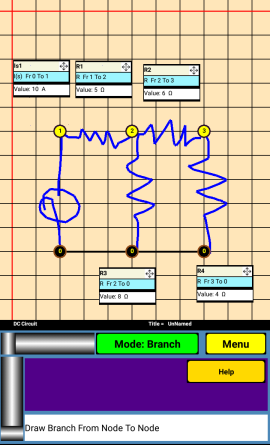
Step 5. Place your finger on node 0 and draw a branch (resistor) from that node to node 2. It will bring up the Branch
mini screen. (See fig 3) Notice that mini screen is partially translucent.

Fig. 3

Note: when drawing branches, it must connect 2 nodes. On the first node you may place your finger close to a node and slide into a node. And once a node has been chosen it will flash, and you can see the branch being drawn as you move your finger. You may occasionally need to lift your finger off the screen, and touch the node you wish to connect.
Step 6. In the yellow [Choose Type] select [R ] for “resistor” to bring up the next screen. See Fig 4.

Fig. 4

Touch the lightly colored box, next to the Value label and this will bring up the keyboard. Enter 6 by Clicking 6 on the keyboard and then the [Return Key] and final the Red [ENTER BR] button. The circuit screen will show an extended label which has the information of the branch just entered

Fig. 5

Touching the branch label can be done in 3 different ways for 3 different functions. You can place your finger on the arrows in the upper right corner of the label box and while not lifting it off the screen, move your finger to a new location and once you have it where you would like, lift your finger. You can also click on the label ( anywhere other than the upper right corner) and it will allow you to modify the information, for that branch. The 3rd function is after a circuit is solved and is explained later in this document.

Fig. 6

Step 7. Enter a branch parallel to the one just entered by again drawing a resistor from node 0 to node 2, and again select Resistor for type and again give it a value of 6
Step 8. Draw a resistor branch from node 2 to node 1 and give it a value of 9.
Step 9. Draw one more branch, a current source from node 0 to Node 2. This time select [ I(s) ] for a current source from node 0 to Node 2. Give it a value of 5.

Fig. 7

You can use the arrows in the upper right corner of the label to move the labels to convenient locations.
You are now ready to solve the circuit, which you have just drawn. Click the [Mode] button, and choose [SOLVE].

Fig. 8

Notice that labels now have an additional line at the bottom, which shows the branch voltage of each branch. There are also some new buttons in the bottom area. These allow you to display the voltage, current and power of each branch. While the program is in display mode, there are some additional features available. You can click on a label and view all the information for the branch at one time. See Fig 9. You can also click on a node and display the node voltage for that node. The 2 screens also have arrows that allow you to scroll through the branch and node information.

Fig. 9

App Functions

The App operates in 4 main modes. [Nodes], [Branches], [Solve], [Display]
This user chooses the mode by the Mode button. After hitting solve the program goes to [Display]
[Nodes] [Branches] modes allow the user to enter nodes and branches respectively.
[Solve] commands the App to solve the circuit.
[Display] displays the solution of the circuit just solved.

Choosing AC or DC, Choosing the Source Frequency. {AC DC only}

The App AC DC operates as either AC or DC, and if AC is chosen, the user must also a frequency for the independent sources. The user first clicks the [Menu] button, and then click the [Circuit Type/Frequency] button. The following screen will appear.

Fig. 10

User should choose AC or DC from the drop-down list and if AC is chosen then to touch the Entry box to enter the numeric frequency. Finally, the user should use the dropdown list which is to the right of the Entry box to choose the frequency multiplier. Choices include htz (ie no multiplier), K for Kilohertz, M for Megahertz, G for Gigahertz, or T for Terahertz. After the user hits the [ENTER] key the App will display the type of Circuit along with the frequency (if applicable) on left side of the black bar, which lies above the [Mode] and [Menu] buttons.
Entering Circuit Data on the Grid [Nodes] [Branches]
The Grid contains 25 horizontal and 25 vertical lines. The first and last horizontal and vertical lines are a different color than the rest. Not all the grid lines can be shown on the grid at once, so 2 scroll bars are includes below the grid, to allow the user can scroll the screen. Nodes must be added at the places where 2 lines intersect.

[Node Mode]

In order to add nodes to the grid, the user must be in the Node mode. The user should check that the mode button (see above) says [Node Mode} and if it does not, they should click that button and select Node from the choices.
The Node Mode allows the user to Add, Delete, and to modify the nodes in several different ways. If the user clicks on an intersection without a node, a node will be added. The very first node will be named 0 and will be the ground node (although the user can later change this) Subsequent nodes will take the next available number. If the user clicks on an existing node, then the node menu shown below will appear

Fig. 11

[Delete Node] The selected Node is deleted
[Rename Node] The user is prompted to give the user a new name.
Note about the naming of nodes. Node names may contain 1 or 2 characters only. Naming a node “0” is the same as making it the ground node. A circuit must have a ground node, which will have a voltage of zero. The other nodes are not restricted. It is possible to give 2 nodes the same name, if you do this then electrically the nodes are the same, and will have the same node voltage. For example the 2 circuits shown below are equivalent. Note nodes can also be stretched

Fig. 12

Stretching a Node

The node menu also give the user the option of stretching a node. Often the ground node in circuit schematics found in books and magazines is stretched along the bottom horizontal. Occasionally other nodes are stretched as well. The Apps allow the user to stretch a node in either the horizontal or vertical direction. Stretching a node in 4 step process.
  • Step 1 Click on the Node that you wish to stretch.
  • Step 2 Choose either Stretch Horizontal or Stretch Vertical. A node can only be stretched in one direction.
  • Step 3. The chosen node will flash. If the user wants to stretch the node horizontally then the user should touch the screen to the right or left on the node. If the node is a single point or already a stretched node it will stretch in that direction. Note: A node cannot be stretched on top of another node.
  • Step 4. The user can now add sub nodes onto the stretched node. Sub nodes are added when a user clicks on a line at a place where a node does not exist. If you click on a sub node (assuming that no branches are connected) it is removed. Up to 6 sub Nodes can be entered, not including the 2 ends of each node
Stretching a node vertically works similarly to horizontally except the node is stretched Up and down rather than right and left.
It is important to note that the end points and the sub nodes of a node is where a branch is to connect to a node. A branch that hits a stretched node anywhere else will not be connected. In the figure below the 2 capacitors connect node 1 and 4. The resistor connects node 2 and node 3, it crosses node 1 but, since it does not a hit a sub node it does not connect to node 1

Fig. 13

[Branch Mode]

Branches in DC In more detail

To draw the branches the user first puts the App in Branch Mode by clicking the Mode button and choosing Branch. For DC Circuits there are 9 types of Branches, which the user can choose.
  • R – Resistor
  • C – Capacitor - note not active in a DC Circuit
  • L – Inductor - note not active in a DC Circuit
  • I(s) – Current Source
  • V(s) – Voltage Source
  • VCCS – Voltage Controlled Current Source
  • VCVS – Voltage Controlled Voltage Source
  • CCCS – Current Controlled Current Source
  • CCVS - Current Controlled Voltage Source
When the user draws a branch connecting 2 nodes they will be given a choice in a dropdown list and should use it to tell the app what kind of branch they have just drawn.
Depending on the type of branch, it may allow for the user to enter additional information. The information to be entered, for each branch is described first This is followed by a description of the specific information required for certain types of branches. See Fig 14

Fig. 14

The first line includes the Entry Box, which holds the name of the Branch. The App chooses a name for the branch depending on the type of Branch, but the user may give the branch a different name. For example the first resistor will given the unimaginative name of R1.
The second line contains the branch type and the nodes (From and To) which the branch contains. These are unchangeable by the user.
The 3rd line is for the Value label, the Value Entry box, the value multiplier and finally the units of the branch. For example the resistor has a multiplier drop down list of nothing, K (for Kilo), or M for Mega; and a resistor has a units of ohms.
Every type of Branch has a checkbox near the bottom, which allows the user to add a line to the branch label with a note
The 4 types of controlled source branches, VCCS, VCVS, CCCS, and CCVS allow for the user to select a branch which controls them. For a Voltage Controlled Source, any type of branch can be a controlled branch, for a Current Controlled Branch, the Control Branch must be a resistor. The control voltage for a control branch is the rise in voltage (which could be negative in value) from the Fr node to the To Node. The control current for a control branch is the current flow (which could be negative in value) from the Fr node to the To Node.
The voltage Source as well as the VCVS, and the CCVS have an addition option that other types of branches don’t have. These have the option of adding a resistor in line with the voltage source or controlled voltage source. Circuits where all Voltage Sources are paired with a resistor in series are in some ways easier for a computer to handle than lone voltage sources, however these Apps can handle both types.

Branches in AC (in more detail)

To draw the branches the user first puts the App in Branch Mode by clicking the Mode button and choosing Branch.
For AC Circuits there are 11 types of Branches, which the user can choose, the same 9 branch types available, plus 2 new types, Z Impedance, and Y Admittance.
For AC Circuits there are 11 types of Branches, which the user can choose.
  • R – Resistor
  • C – Capacitor
  • L – Inductor
  • Z - Impedance
  • Y - Admittance
  • I(s) – Current Source
  • V(s) – Voltage Source
  • VCCS – Voltage Controlled Current Source
  • VCVS – Voltage Controlled Voltage Source
  • CCCS – Current Controlled Current Source
  • CCVS - Current Controlled Voltage Source
Depending on the type of branch, it may allow for the user to enter additional information. The information to be entered, for most branch is described first This is followed by a description of the specific information required for certain types of branches. See Fig 15

Fig. 15

The first line includes the Entry Box, which holds the name of the Branch. The App chooses a name for the branch depending on the type of Branch, but the user may give the branch a different name For example the first resistor will given the unimaginative name of R1.
The second line contains the branch type and the nodes (From and To) which the branch contains. These are unchangeable by the user.
The 3rd line is for the Value label, the Value Entry box, the value multiplier and finally the units of the branch. For example the resistor has a multiplier drop down list of nothing, K (for Kilo), or M for Mega; and a resistor has a units of ohms.
Every type of Branch has a checkbox near the bottom, which allows the user to add a line to the branch label with a note
The types of I(s) Current Source and V(s) Voltage Source, in the AC circuit, have an additional Entry Box and Drop Down List which allows the user to enter the Numeric Angle and the units of the angle, (in degrees or in radians)

Fig. 16

The 4 types of controlled source branches, VCCS, VCVS, CCCS, and CCVS allow for the user to select a branch which controls them. For a Voltage Controlled Source, any type of branch can be a controlled branch, for a Current Controlled Branch, the Control Branch must be a resistor. The control voltage for a control branch is the rise in voltage (which could be negative in value) from the Fr node to the To Node. The control current for a control branch is the current flow (which could be negative in value) from the Fr node to the To Node.
The voltage Source as well as the VCVS, and the CCVS have an addition option that other types of branches don’t have. These have the option of adding a resistor in line with the voltage source or controlled voltage source. Circuits where all Voltage Sources are paired with a resistor in series are in some ways easier for a computer to handle than lone voltage sources, however these Apps can handle both types.
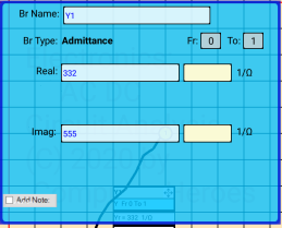
The final 2 Branch Types (Z – Impedance, Y – Admittance) follow a slightly different format than the others The 1st 2 lines are the same, and the last line to add a note are the same, but instead of a single Value line with a Multiplier drop box, these types have 2 input boxes each with an associated drop box, to allow for the input of a Real and Imaginary part of the impedance or Admittance.

Fig. 17

Modifying a Branch

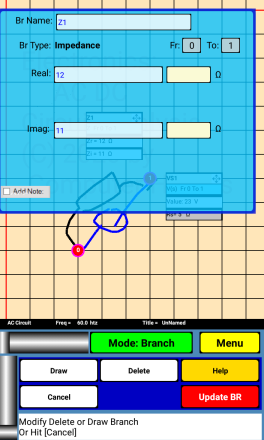
When a user has finished entering a branch, and has not hit the 1st node for the next branch (or when previous branches have been entered, and the user comes back to Branch Mode) The user may modify a branch by clicking on a branch’s label. A screen similar to the Branch entry screen will come up.

Fig. 18

Notice that the buttons in the lower part of the screen are slightly different than the buttons for ENTERING a branch. The user may hit [Delete] to delete the branch completely. He may hit [Cancel] to leave the branch alone. The user may modify the screen data and then [UPDATE] the Branch. Finally the user may also draw more drawing strokes onto the branch by clicking the [DRAW] button. There is no way to undrawn anything, There is also no way to change the type of a branch. If you want to do that, you should delete the existing branch and then enter a new branch in it’s place.
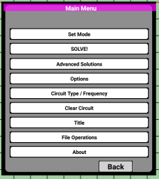
[Options]

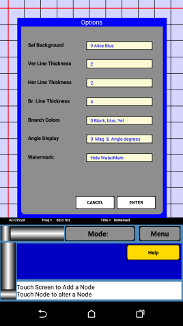
The following Screen is show.

Fig. 20

  • Set Background – Allows the user to Change the color of the circuit drawing area.
  • Ver Line Thickness - Allows the user to Change the width of the vertical lines
  • Hor Line Thickness - Allows the user to Change the width of the horizontal lines
  • Br Line Thickness - Allows the user to Change the width of the drawn branches
  • Branch Colors – colors used for the branches. The first color is the main color and is the color of the drawn branches, the 2nd color is the one used while a branch is being drawn, and the last color is the color used when moving a label.
  • Angle Display – This option is only applicable to AC Circuits. The user can choose how voltages and currents are displayed. There are 4 options
    • 0 – Voltage and Current are displayed with magnitude and angle with the angle in degrees
    • 1 - Voltage and Current are displayed with magnitude and angle with the angle in radians
    • 2 - Voltage and Current are displayed with real & imaginary parts, and degrees are used on the detail page
    • 3 - Voltage and Current are displayed with real & imaginary parts, and radians are used on the detail page
  • WaterMark - Shows or hides the Watermark shown on the circuit drawing area.

[Special Features only Electronics AC DC Circuit Analysis App]

There are 2 additional features that AC DC version of the program has that the DC version does not. In the AC DC version only, both these features can be used on either AC or DC circuits.

[Norton/Thevenin]

To find the Norton and Thevenin equivalent of a circuit, the user should hit [Menu] [Advanced Solution] [Norton/Thevenin]

Fig. 21

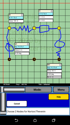
The App will now display in the display window at the bottom:
Choose 2 Nodes for Norton/Thevenin.
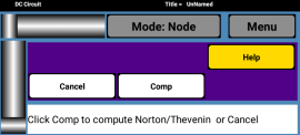
The user should hit 2 nodes and the following will appear in the button tray and the display box.

Fig. 22

The user should hit [Comp]
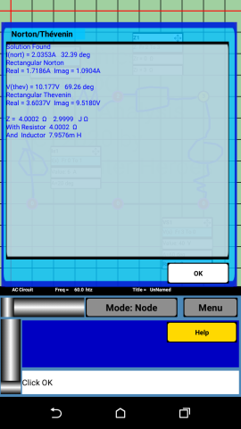
The App will display in the screen the Norton and Thevnin solutions.

Fig. 23

[Circuit Equations]

To find the Norton and Thevenin equivalent of a circuit, the user should hit [Menu] [Advanced Solution] [Circuit Equations]

Fig. 24

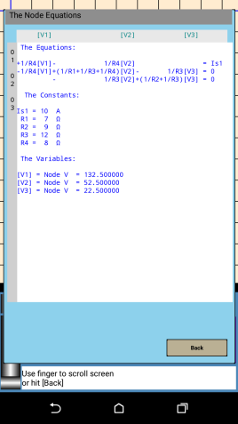
And the circuit equations will be displayed.

Fig. 25

[Contacting Us]

Comments about these Apps. You may contact us at:
computerheroes07@gmail.com

[FAQs]

Q. When Drawing a Branch from node to node, sometimes it doesn’t bring up the branch page.
Ans. Yes, sometimes this happens. Usually when you slide into a node, the App will act properly, but occasionally you may need to slide into the node again, or you may need to lift your finger and then actually touch the 2nd node.

Q. How big a circuit can the App Handle?
Ans. You may enter circuits with up to 24 branches, and 20 nodes. You cannot display the node equations of a circuit with more than 5 branches

Q. Can you draw say a [resistor] and then choose say [Current Source] as the branches type.
Ans. Yes, although this would be confusing it is possible to do this.

[Programs from Computer Heroes LLC]

[Electronics DC Circuit Analysis App]

This App will allow you to draw a DC Circuit on a grid, to solve the circuit and display node voltages, branch voltages, branch currents and branch powers. Branches may be current sources, voltage sources (with or without a built in resistor in series), resistors, or 4 types of controlled sources VCCS, CCCS, VCVS, CCVS

[Electronics AC DC Circuit Analysis App]

coming soon! [Anticipated release Sept 4, 2020]

The Apps can do everything the DC app can do, PLUS
Can also solve AC Circuits.
Allows Additional types of branches Impedance and Admittance
Can Show Circuit Equations for both AC and DC Circuits
Can compute the Norton and Thevenin equivalent for both AC and DC Circuits

[Disclaimer]

The Apps are for educational, and academic use only. Computer Heroes LLC accepts no liability for and damage or injury resulting from using these Apps or the results of these Apps. User should verify any results from the program before making or modifying any type of electronic constructions. Any reliance you place on the results of these apps is therefore strictly at your own risk.

Copyright 2020 by Computer Heroes, all right reserved