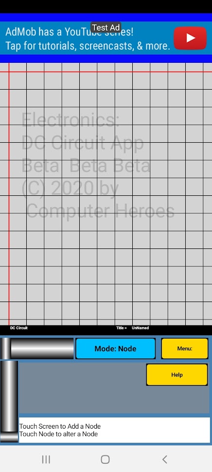
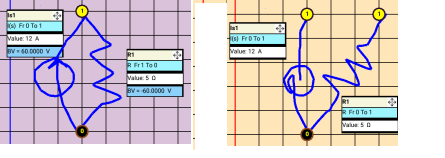
The screen will come up blank (Fig. 1) The Mode button will be blue, and it will say DC Circuit on the black bar
above that button.
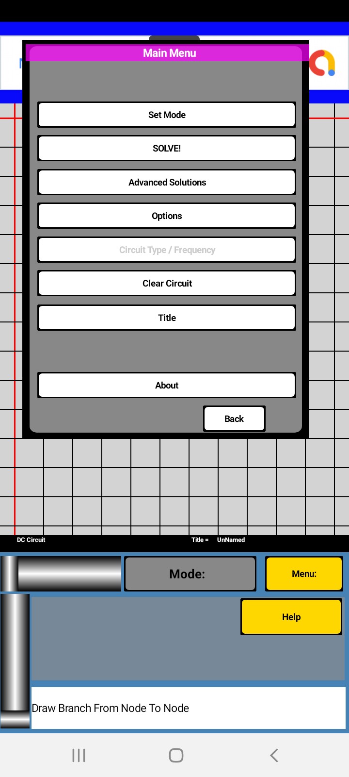
Note: If the Mode button does not say [Node], you should press that button, and on the screen that pops up press [Node]
Note If the screen is not clear, then you can clear it by pressing the [Menu] button, and on the screen that pops up
press [Clear Circuit]
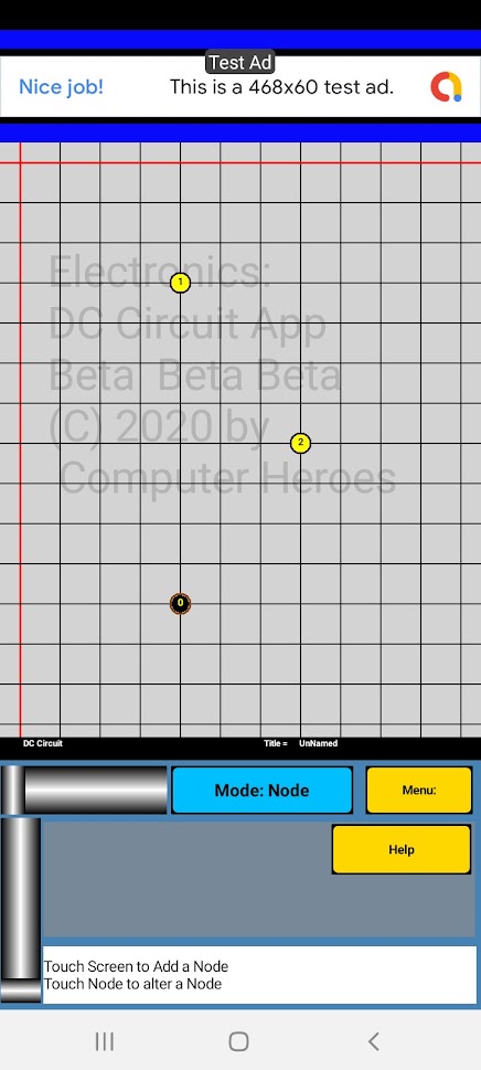
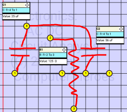
Near the bottom of the screen towards the left side (see fig .2) touch on an intersection of the horizontal and vertical
lines. The program will add a black circle with the number 0 in the middle. This is the ground node.
Step 2. Add a 2nd node by touching another intersection of the vertical and horizontal lines, this one near the top
of the screen and above the ground node. (See fig 2)
Step 3. Add the 3rd node, once again by touching the intersection of 2 lines, this one to the right of the 2 previous
nodes, and between them vertically. (See fig 2)
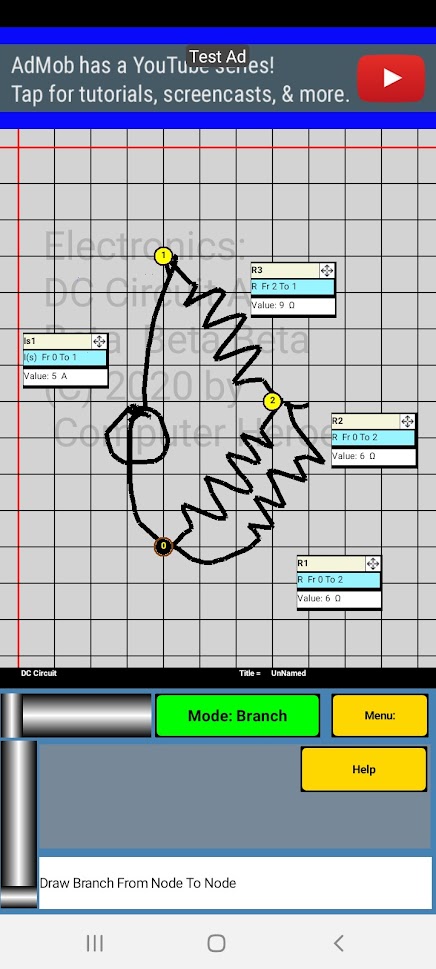
Step 4. Now we need to draw the branches between the nodes, so we must change the mode from [Node] to [Branch]. Click
the [Mode] button to bring up the [Choose Mode] screen. And click Branches.
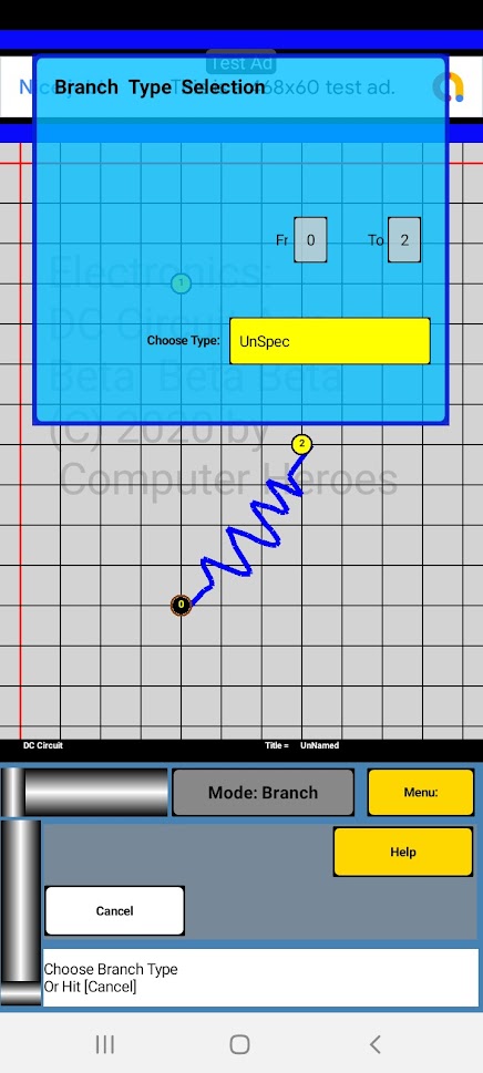
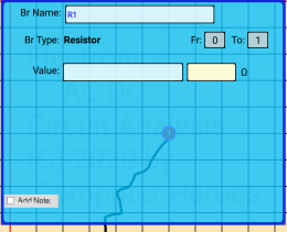
Step 5. Place your finger on node 0 and draw a branch (resistor) from that node to node 2. It will bring up the Branch
mini screen. (See fig 3) Notice that mini screen is partially translucent.
Note: when drawing branches, it must connect 2 nodes. On the first node you may place your finger close to a node and
slide into a node. And once a node has been chosen it will flash, and you can see the branch being drawn as you move your
finger. You may occasionally need to lift your finger off the screen, and touch the node you wish to connect.
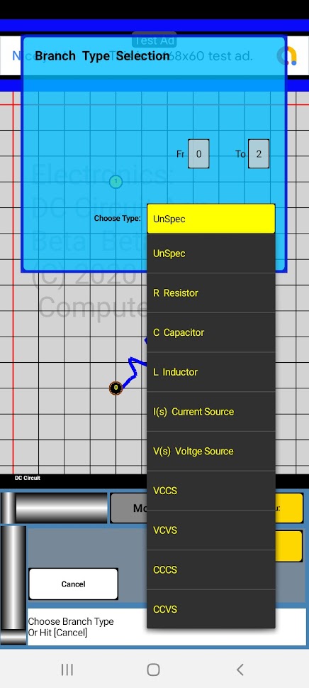
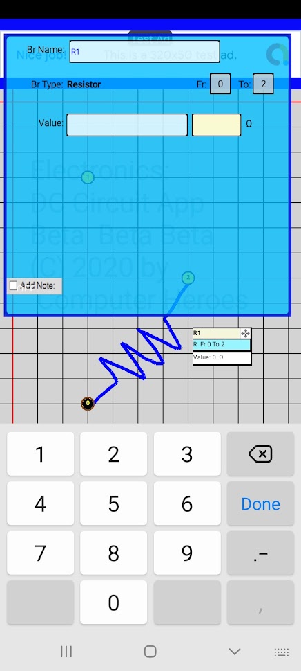
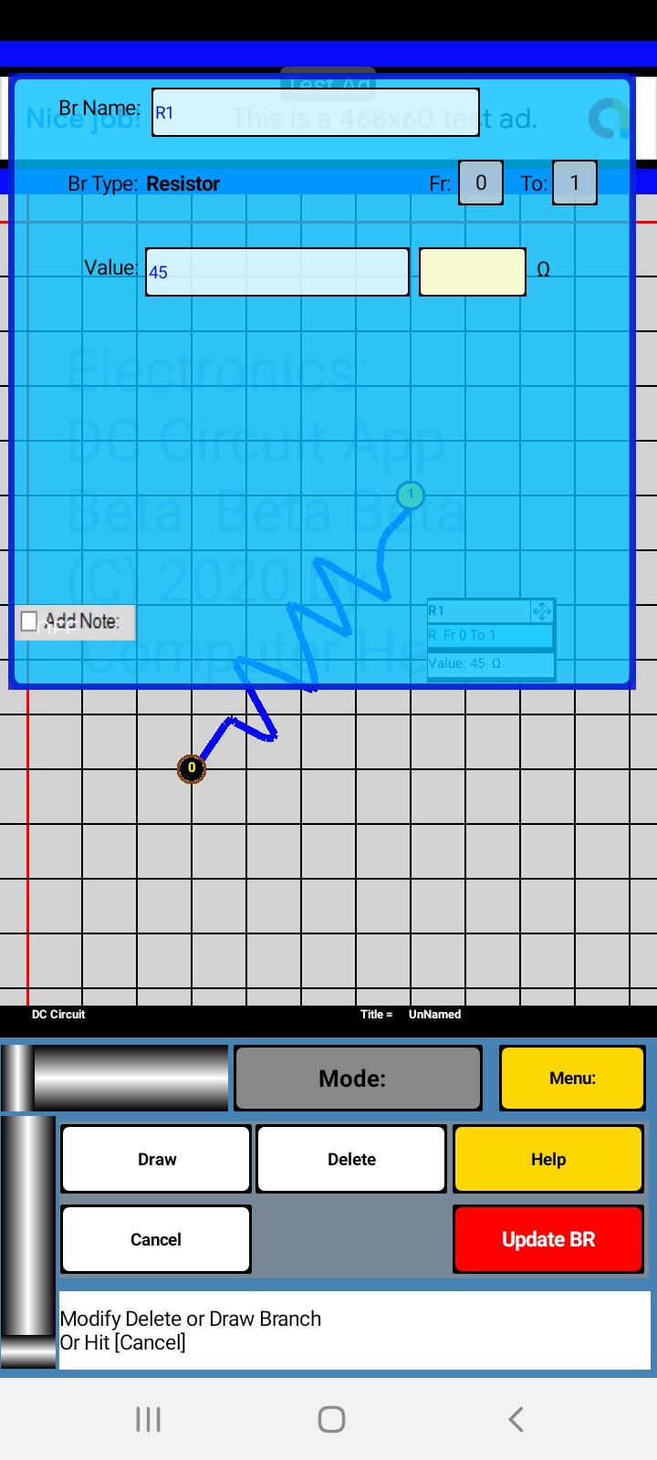
Step 6. In the yellow [Choose Type] select [R ] for “resistor” to bring up the next screen. See Fig 4.
Touch the lightly colored box, next to the Value label and this will bring up the keyboard. Enter 6 by Clicking 6 on the
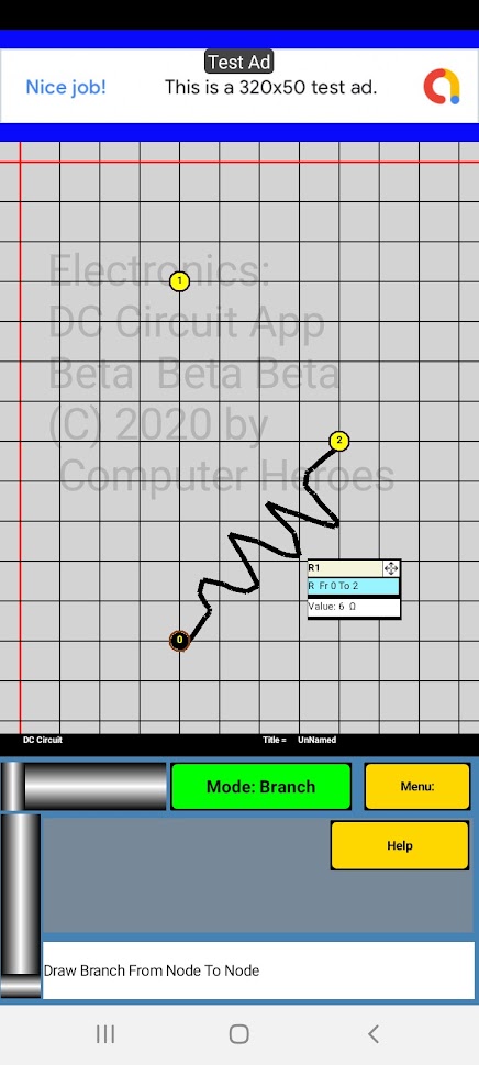
keyboard and then the [Return Key] and final the Red [ENTER BR] button. The circuit screen will show an extended label which
has the information of the branch just entered
Touching the branch label can be done in 3 different ways for 3 different functions. You can place your finger on the arrows
in the upper right corner of the label box and while not lifting it off the screen, move your finger to a new location and
once you have it where you would like, lift your finger. You can also click on the label ( anywhere other than the upper
right corner) and it will allow you to modify the information, for that branch. The 3rd function is after a circuit is solved
and is explained later in this document.
Step 7. Enter a branch parallel to the one just entered by again drawing a resistor from node 0 to node 2, and again select
Resistor for type and again give it a value of 6
Step 8. Draw a resistor branch from node 2 to node 1 and give it a value of 9.
Step 9. Draw one more branch, a current source from node 0 to Node 2. This time select [ I(s) ] for a current source from node
0 to Node 2. Give it a value of 5.
You can use the arrows in the upper right corner of the label to move the labels to convenient locations.
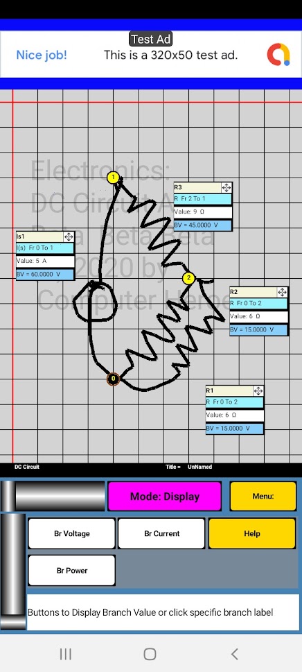
You are now ready to solve the circuit, which you have just drawn. Click the [Mode] button, and choose [SOLVE].
Notice that labels now have an additional line at the bottom, which shows the branch voltage of each branch. There are also some
new buttons in the bottom area. These allow you to display the voltage, current and power of each branch. While the program is
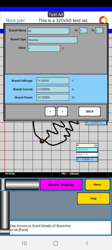
in display mode, there are some additional features available. You can click on a label and view all the information for the
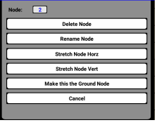
branch at one time. See Fig 9. You can also click on a node and display the node voltage for that node. The 2 screens also have
arrows that allow you to scroll through the branch and node information.
